Buenas Haxors!
Tal y como hicimos con la Box 1 este mes os traemos la review de la BOX #2 de @thehackersgarage. Sin duda, si la anterior os gusto abrochaos los cinturones porque este mes el esbirro se ha puesto las botas con su contenido! Esta vez podemos incluso contaros mas ya que hemos podido asistir al taller impartido por @da3n3rys y @infiltrandome de los cuales podemos decir que son unas grandes personas y si cabe mayores profesionales!
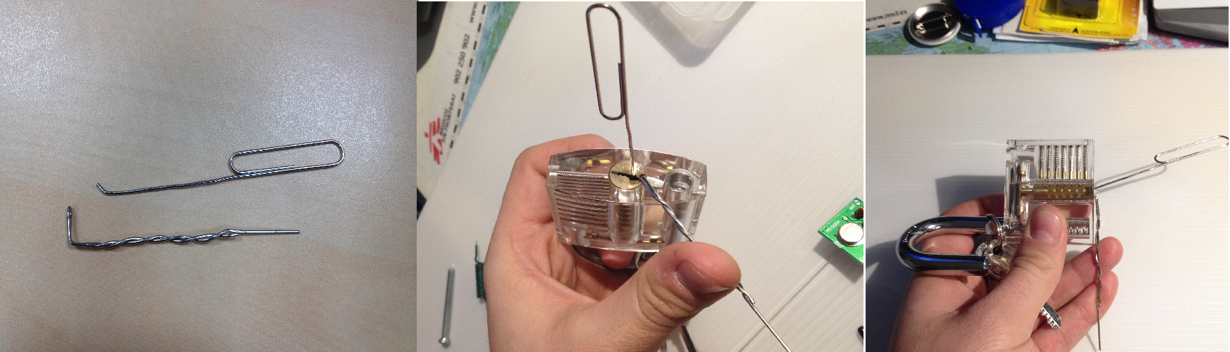
La abrimos y que encontramos? Para empezar vemos un MEGACANDADO transparente … que esta esperando a que un ávido hacker intente abrirlo utilizando sus dotes de lockpicking (cosa que esta vez los compañeros de Hackersgarage nos han enseñado como hacer una bonitas clip-ganzuas) …. ¿Seras tu capaz? Y junto a eso una especie de tarjeta multiusos llamada NINJA WALLET! que a decir verdad mola demasiado!
«Amo! Mireeee me he quitado los grilletes! Ve? soy un Esbirro libreeeee! emmm… no me joda no soy un elfo domestico como Dobi… no me tire sus asquerosos calcetines!»
Después de esto encontramos 2 proyectos diferenciados, pero antes vamos a ver un poco la teoría tras «La caja #2»:
TEORÍA DE LA CAJA (¿o creíais que esto es montar piezas de LEGO?)
Vale vale me dejo ya de chapa… (con lo bonito que os lo pongo…)
«Menudo coñazo tio! metete al rollo y no nos pegues chapa… que para eso ya tengo al amo comiendome la oreja»
Proyecto 1 – DIY 433 Mhz Transceiver
Vale el nombre suena a chino… traducido de elfico a lengua común es un dispositivo con el cual seremos capaces de snifar(capturar… que nos encantan estas palabrejas raras) los datos enviados por un mando de toda la vida de los de los garajes(por ejemplo), guardar esa señal y después replicarla ¿así sencillo verdad?
Vale como ya tenemos ciertos conceptos sobre que es SDR.. y que podemos hacer con ello… y sabemos que pieza es que, aaaal turron!!
Paso 1 – Probando Probando
Como siempre que tengamos un arduino nuevo en las manos o uno que llevemos tiempo sin utilizar lo que vamos a hacer es probar que funciona con el programa de ejemplo BLINK como hicimos la vez anterior. Esta vez la única diferencia es que la placa que hemos recibido es una ARDUINO UNO con lo que hay que 1º instalar los drivers pertinentes… (o impertinentes dependiendo quien los instale ;P) y configurar el IDE correctamente para que pueda funcionar en nuestro sistema y no nos de errores.
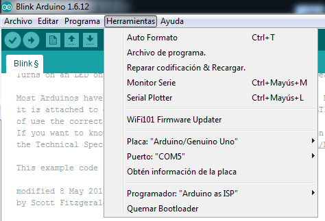
Entiendo que a estas alturas todos sabemos configurarlo para que funcione correctamente pero por si acaso tenemos algún lector despistado…. os pongo las imágenes. Como podeis ver seleccionamos ARDUINO/GENUINO UNO» y después tenéis que mirar bien el puerto al que lo conectáis… ya que si no teneis instalados los drivers… os saldrá algo de wifi o bluetooth que nada tiene que ver con lo que pretendemos hacer aquí… y PETARÁ
Tras este paso , verificamos que todo funciona de forma correcta ejecutando el código de ejemplo BLINK… venga a ver quien pone el parpadeo mas «mascachapas» (eh @rtortuga) probad a variar la velocidad de 1000 a 100 y tenéis una discoteca de bolsillo!
Bueno esto es fácil, ya nos funciona la placa así que vamos a probar los sensores.
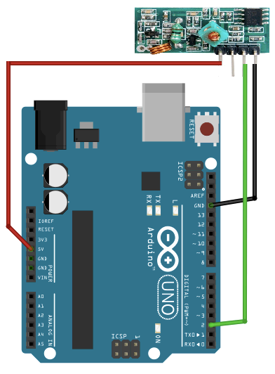
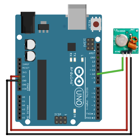
Nos dan un esquema en el cual nos marcan ya como conectar el receptor de 443mgz a la placa arduino… como en bricomania, FÁCIL SENCILLO Y PARA TODA LA FAMILIA!
Antes de poneros a conectar nada… acordaros de desconectar la placa arduino del ordenador… no queremos que montéis una barbacoa… ni que os queméis la mano ni nada por el estilo… Antes de conectar nada al pc de nuevo bajaremos las librerias necesarias para este paso… sino se darán caso de WTF! ya me ha petado esto! si esque soy un negao!
Receptor – Arduino
VCC -> 5V
GND -> GND
DATA -> D2
«Mierda me has jodido la broma al amo! Yo que queria que se sintiera mas inutil de lo que ya es!»
Ahora nos queda hacer la prueba de si todo funciona así que lo conectamos, probamos que el puerto esta bien configurado y abrimos el código que necesitamos que se encuentra en EJEMPLOS-> RC-SWITCH->Receivedemo_Advance y subimos el codigo a la placa
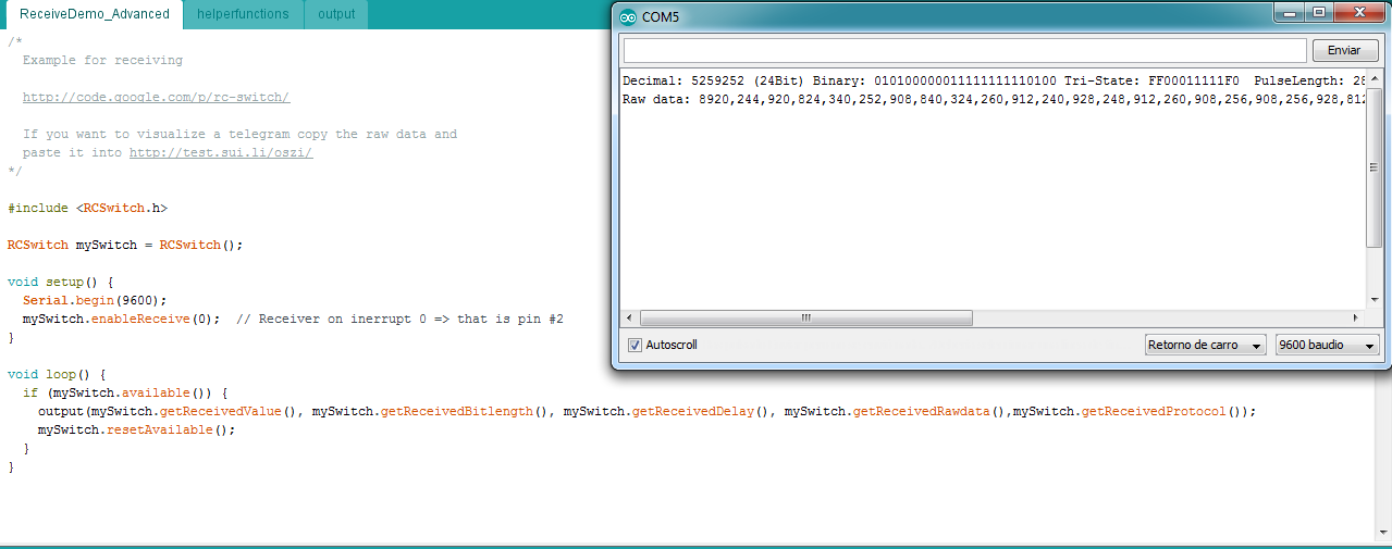
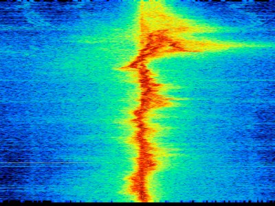
Vale! y diréis que es eso del lateral tío? pues el monitor serie que trae IDE… lo usaremos para ver si realmente funciona la instalación que hemos hecho pulsando en los botones del mando de garaje que recibimos en la caja!
«Amo pero que narices ha hecho! Esta todo mal conectado! ¿QUE? Madre mía y ahora salta la alarma anti incendios! si es que podría hacer pinchos morunos en esta placa so gañan!»
Si os sale eso en pantalla cuando tengáis todo conectado y subido, Minipunto para vosotros ya habéis avanzado un trozo mas!
Ahora nos toca probar el EMISOR y aquí es cuando la mataron… en circunstancias normales… esto no seria posible ya que, como narices miro a ver si recibe datos si resulta que estoy usando el arduino para emitirlos? Pues bien… nosotros jejeje afortunados acudimos al taller de @hackersgarage en Guadalajara … y pudimos verlo en directo pero para que veáis el funcionamiento completo… he montado el receptor en un arduino que tenia por la mesa de trabajo (PISTA: Podéis usar la placa del proyecto anterior … digo no? ;P) de forma que podamos ver ambas partes interaccionando entre ellas. Configurad el anterior arduino u otro como hemos explicado arriba… y vamos a por el emisor.
Aquí tenemos el esquema que nos proporcionan las instrucciones de montaje, si, otra vez muy facilito verdad solo es poner los cablecillos en su lugar y conectar al pc otra vez para esta vez subir el código. En este caso vamos a utilizar EJEMPLOS -> RC-SWITCH->EmiterDemo.
Emisor – Arduino
VCC -> 5V
GND -> GND
DATA -> D10
Como apunte divertido e interesante podemos decir que el mensaje que emitimos podemos cambiarlo pudiendo lanzar incluso Strings que se verían en el receptor…
Bien otro minipunto para todos vosotros! a este paso os conseguís el puntaco entero!
Vale tenemos ya probados los 2 módulos receptor y emisor, ahora vamos con la pantalla TFT Tactil . Este tema al parecer es algo delicado ya que existen 2 modelos diferentes de pantalla:
- ILI9325/9328 que para los que no entendemos de esto se resume a : LA PANTALLA CON 4 botoncitos
- ILI9341 que es una pantalla parecida pero con 5 botoncitos…(que es la que voy a usar… y creedme que os digo que encarna al mismisimo SATAN!)
«jijijijiij Amoooooooo mireeeee hemos encontrado algo que rivaliza con nuestra malignidad… y es mas pequeño! PANTALLITAS A MI!!!!!!!!»
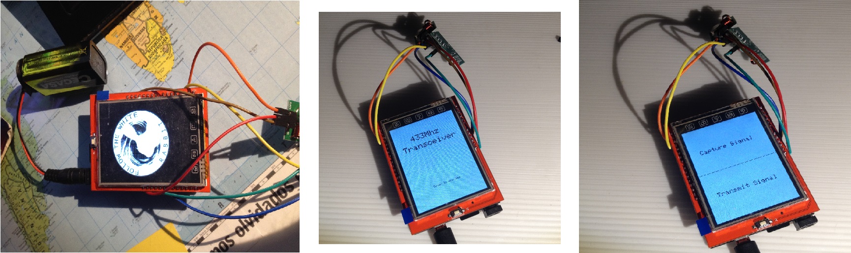
Vamos a hacer una prueba con la pantalla para ello … conectamos la pantalla a la placa… sin miedo! se ve claramente como hacerlo ;P nos bajamos los drivers correspondientes a nuestra pantalla y probamos entre las diferentes opciones algo que nos llame la atención… en mi caso probé tanto a mostrar gráficos aleatorios como a usar tftpaint que me hizo volver a la infancia cuando solo me dejaban usar paint en el ordenador.
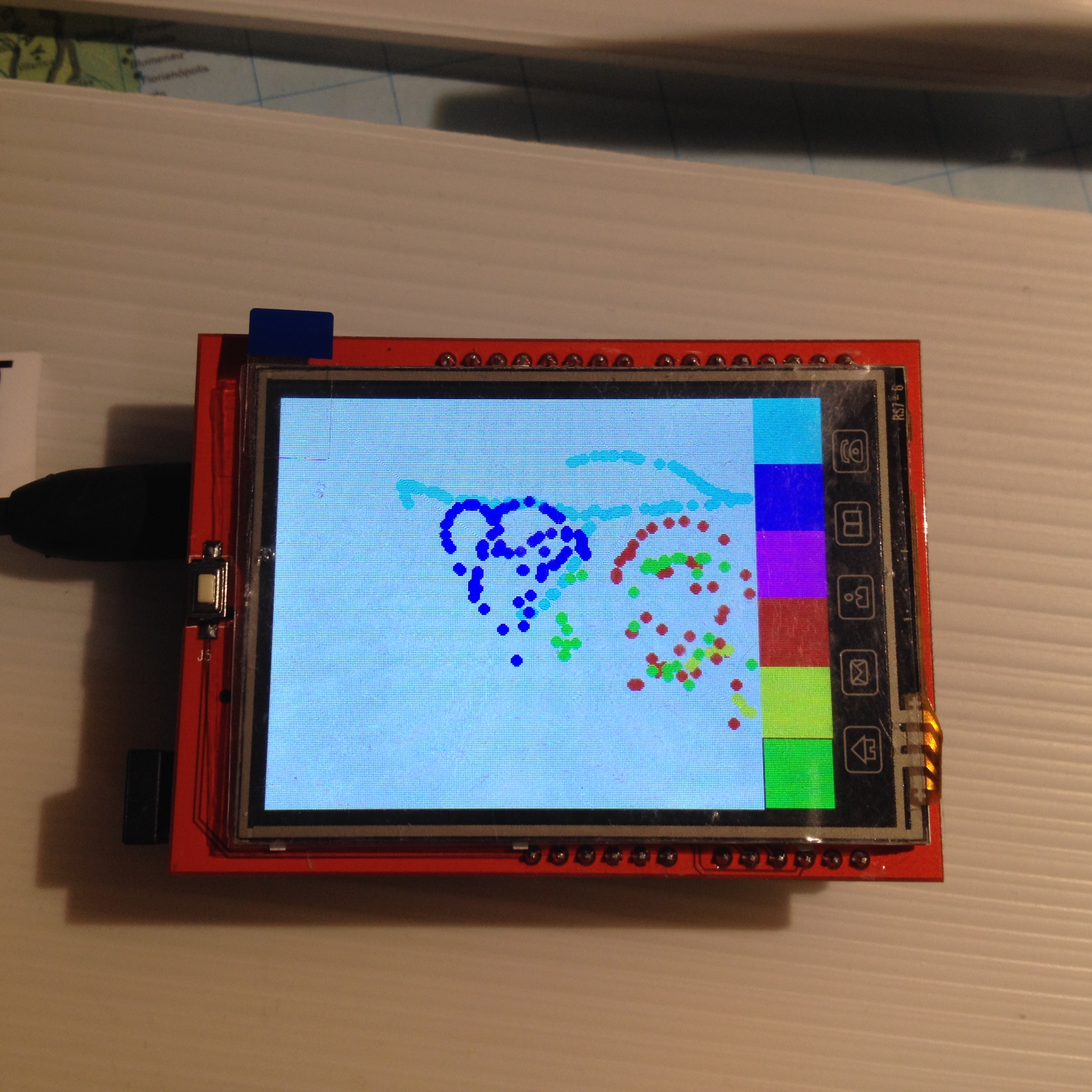
Pero que simpática la pantallita con colorines jajajajja me encanta pintar con el dedo en ella… aunque claro… como es malvada…. no me ha dejado dibujar un p….
Se nos dan varios problemas, al menos en mi caso así ha sido. para empezar… entiendo que el display se me ve al revés porque los botones me quedan en la parte superior y parecen estar invertidos … por lo que buscando encuentro esto que indica que solo tengo que modificar en el código el siguiente valor para girar 180º la pantalla :
tft.setRotation(2);
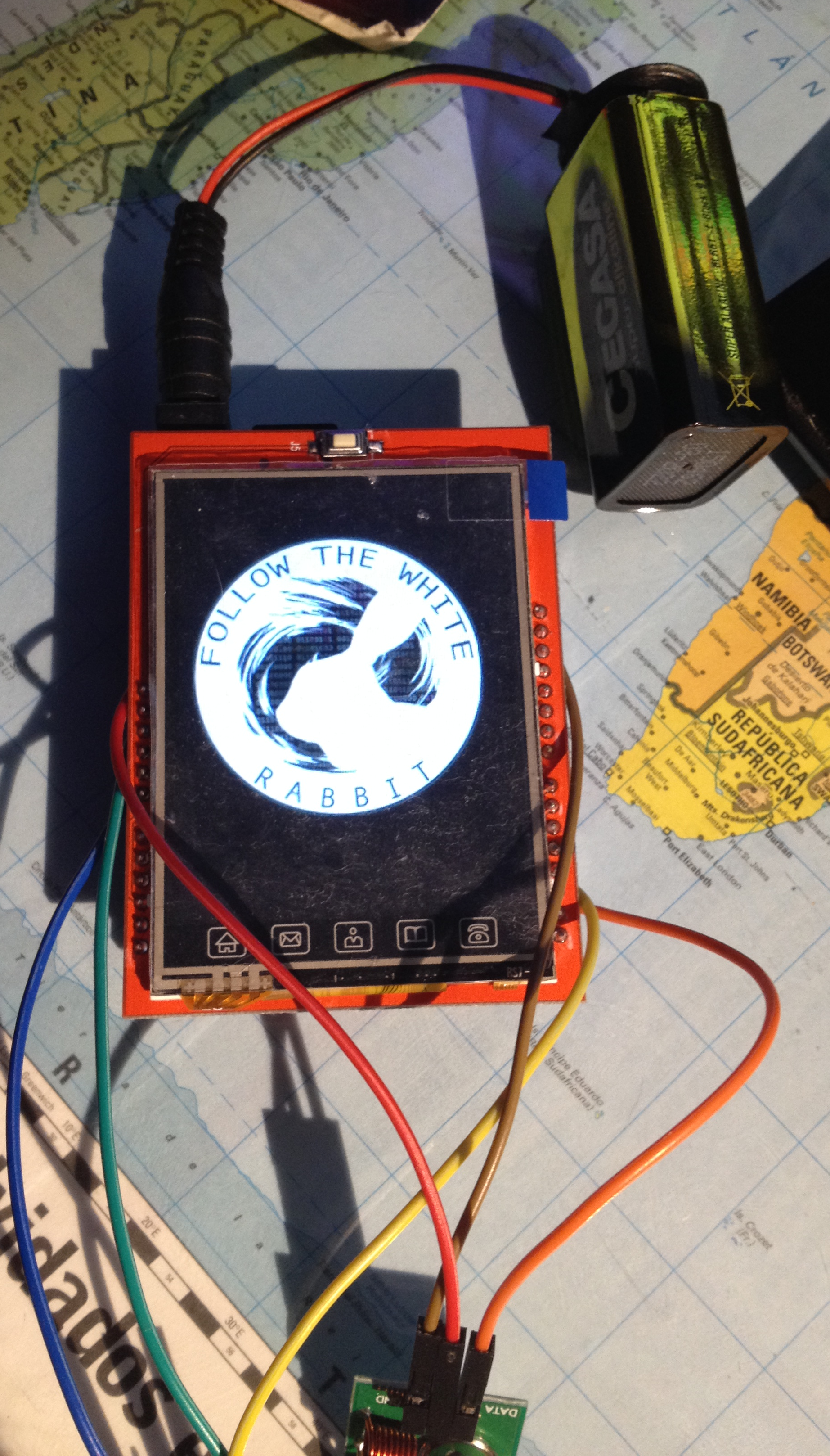
Otro de los fallos que me da es que al arrancar, la imagen que se muestra (jijiji si @Da3nerys… la hemos cambiado por el conejito) , nos sale con los colores invertidos… algo sencillo de solucionar ya que se trata solo de cambiar parámetros… o si nos da igual… simplemente hacer un negativo de la imagen que metamos en la SD.
El problema que podríamos tener de tema de inversión de ejes nos lo ha dado ya solucionado en el código final la propia @Da3nerys si es que esta chica esta en todo!
Vale para terminar de montar todo… 2 apuntes básicos…
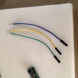
1º – Nos va a tocar pelar los cables si o si… así que paciencia… no os embaleis… y si… esos cables que antes metiais en las ranuras de la placa arduino.. ahora van en la misma ranura y despues plantais la pantalla encima… SIN MIEDO!
2º – No me seáis vagos! Y curraos la antena que no cuesta nah!
Después de terminar de montar el contenido de la caja al probar el montaje nos encontramos con un problema mas aparte de las piedras que nos hemos topado pos el camino, resulta que si pulsamos en enviar no pasa nada pero si por el contrario pulsamos en RECIBIR el «cacharro» peta y se queda totalmente bloqueado teniendo que reiniciarlo. Para comprobar esto, solo tenéis que mantener conectado al PC arduino , y con el IDE abierto abrir el monitor de serie y observar lo que ocurre al pulsar las diferentes opciones en pantalla.
» Ai amo si ya decia yo que su neurona rebotante no daba para mas…. madre mia… pues claro! Se trata de un bucle infinito! que en alguna de las iteraciones hace que pegue un cuelque total …. mas o menos como usted cuando babea viendo imagenes de Ovejas en Bikini…. aiiiiii no me pegueeeee noooooo! noooo!»
Para ello uno de los clientes de Hackersgarage (david.rojo.gonzalez) nos compartió a través del foro varios fragmentos de código que había que insertar en el que ya teníamos . Con esta nueva implementacion evitamos que el programa entre en un bucle infinito y pete.
Aquí os dejamos el código con las mejoras para que funcione:
1 2 3 4 5 6 7 8 9 10 11 12 13 14 15 16 17 18 19 20 21 22 23 24 25 26 27 28 29 30 31 32 33 34 35 36 37 38 39 40 41 42 43 44 45 46 47 48 49 50 51 52 53 54 55 56 57 58 59 60 61 62 63 64 65 66 67 68 69 70 71 72 73 74 75 76 77 78 79 80 81 82 83 84 85 86 87 88 89 90 91 92 93 94 95 96 97 98 99 100 101 102 103 104 105 106 107 108 109 110 111 112 113 114 115 116 117 118 119 120 121 122 123 124 125 126 127 128 129 130 131 132 133 134 135 136 137 138 139 140 141 142 143 144 145 146 147 148 149 150 151 152 153 154 155 156 157 158 159 160 161 162 163 164 165 166 167 168 169 170 171 172 173 174 175 176 177 178 179 180 181 182 183 184 185 186 187 188 189 190 191 192 193 194 195 196 197 198 199 200 201 202 203 204 205 206 207 208 209 210 211 212 213 214 215 216 217 218 219 220 221 222 223 224 225 226 227 228 229 230 231 232 233 234 235 236 237 238 239 240 241 242 243 244 245 246 247 248 249 250 251 252 253 254 255 256 257 258 259 260 261 262 263 264 265 266 267 268 269 270 271 272 273 274 275 276 277 278 279 280 281 282 283 284 285 286 287 288 289 290 291 292 293 294 295 296 297 298 299 300 301 302 303 304 305 306 307 308 309 310 311 312 313 314 315 316 317 318 319 320 321 322 323 324 325 326 327 328 329 330 331 332 333 334 335 336 337 338 339 340 341 342 343 344 345 346 347 348 349 350 351 352 353 354 355 356 357 358 359 360 361 362 363 364 365 366 367 368 369 370 371 372 373 374 375 376 377 378 379 380 381 382 383 384 385 386 387 388 389 390 391 |
#include <RCSwitch.h> #include <SPFD5408_Adafruit_GFX.h> // Core graphics library #include <SPFD5408_Adafruit_TFTLCD.h> // Hardware-specific library #include <SPFD5408_TouchScreen.h> #include <SPI.h> #include <SD.h> #if defined(__SAM3X8E__) #undef __FlashStringHelper::F(string_literal) #define F(string_literal) string_literal #endif #define WHITE 0x0000 #define YELLOW 0x001F #define CYAN 0xF800 #define MAGENTA 0x07E0 #define RED 0x07FF #define GREEN 0xF81F #define BLUE 0xFFE0 #define BLACK 0xFFFF #define SD_CS 10 #define YP A1 // must be an analog pin, use "An" notation! #define XM A2 // must be an analog pin, use "An" notation! #define YM 7 // can be a digital pin #define XP 6 // can be a digital pin #define D3 3 #define D2 2 #define LCD_CS A3 #define LCD_CD A2 #define LCD_WR A1 #define LCD_RD A0 // optional #define LCD_RESET A4 // Calibrate values #define TS_MINX 125 #define TS_MINY 85 #define TS_MAXX 965 #define TS_MAXY 905 int MODE_RECEIVING =0; // VARIABLE QUE INDICA SI ESTA EN MODO CAPTURA int matrix[4][4] = { {0, 0, 0, 0}, {0, 0, 0, 0}, {1, 1, 1, 1}, {1, 1, 1, 1}, }; int value=5555555, bitlength=24; // example // For better pressure precision, we need to know the resistance // between X+ and X- Use any multimeter to read it // For the one we're using, its 300 ohms across the X plate TouchScreen ts = TouchScreen(XP, YP, XM, YM, 300); RCSwitch mySwitch = RCSwitch(); Adafruit_TFTLCD tft(LCD_CS, LCD_CD, LCD_WR, LCD_RD, LCD_RESET); void setup(void) { Serial.begin(9600); Serial.println(F("433Mhz Transceiver test")); tft.reset(); tft.begin(0x9341); // SDFP5408 tft.setRotation(2); Serial.print(F("Initializing SD card...")); if (!SD.begin(SD_CS)) { Serial.println(F("failed!")); return; } Serial.println(F("OK!")); bmpDraw("logo.bmp", 0, 0); delay(1000); // Initial screen tft.fillScreen(WHITE); tft.setCursor (60, 50); tft.setTextSize (3); tft.setTextColor(BLACK); tft.println("433Mhz"); tft.setCursor (22, 85); tft.println("Transceiver"); tft.setCursor (75, 250); tft.setTextSize (1); tft.setTextColor(BLACK); tft.println("Pulsa para continuar"); // Wait touch waitOneTouch(); // Paint drawGUI(); // Pin configuration pinMode(13, OUTPUT); pinMode(D3, INPUT); pinMode(D2, OUTPUT); mySwitch.enableReceive(1); //interrupt 1 == D3 mySwitch.enableTransmit(2); // D2 //Seems weird, but without this it doesnt work mySwitch.send(value, bitlength); mySwitch.resetAvailable(); } #define MINPRESSURE 10 #define MAXPRESSURE 1000 void loop(){ //=========CODIGO NUEVO============ int x, y; int received = 0; static int anterior = 0, actual; static unsigned long int tanterior = 0, tactual = 0; digitalWrite(13, HIGH); TSPoint p = ts.getPoint(); digitalWrite(13, LOW); mySwitch.resetAvailable(); // if sharing pins, you'll need to fix the directions of the touchscreen pins //pinMode(XP, OUTPUT); pinMode(XM, OUTPUT); pinMode(YP, OUTPUT); //pinMode(YM, OUTPUT); // we have some minimum pressure we consider 'valid' // pressure of 0 means no pressing! if (MODE_RECEIVING == 1){ if (mySwitch.available()) { Serial.print(F("Received ")); value = mySwitch.getReceivedValue(); Serial.print(value); Serial.print(F(" / ")); bitlength = mySwitch.getReceivedBitlength(); Serial.print(bitlength); Serial.print(F("bit ")); Serial.print(F("Protocol: ")); Serial.println( mySwitch.getReceivedProtocol() ); mySwitch.resetAvailable(); MODE_RECEIVING = 0;} } if (p.z > MINPRESSURE && p.z < MAXPRESSURE) { p.x = map(p.x, TS_MINX, TS_MAXX, 0, tft.width()); p.y = map(p.y, TS_MINY, TS_MAXY, 0, tft.height()); x = (4 * p.x) / tft.width(); y = (4 * (tft.height() - p.y)) / tft.height(); Serial.println(x); Serial.println(y); actual = matrix[y][x]; Serial.println(actual); tactual = millis(); if (tactual - tanterior > 1000) { tanterior = tactual; anterior = -1; } if (actual != anterior ) { anterior = actual; // we get "actual" as our touchpoint result // and map it with our matrix and matrixc to decide // the pressed button //COMENTADO Y SUSTITUIDO POR EL CODIGO SIGUIENTE // switch (actual) // { // case 0: // while(!received){ // if (mySwitch.available()) { // Serial.print(F("Received ")); // value = mySwitch.getReceivedValue(); // Serial.print(value); // Serial.print(F(" / ")); // bitlength = mySwitch.getReceivedBitlength(); // Serial.print(bitlength); // Serial.print(F("bit ")); // Serial.print(F("Protocol: ")); // Serial.println( mySwitch.getReceivedProtocol() ); // received = 1; // } // } // break; // case 1: // mySwitch.send(value, bitlength); // delay(1000); // break; // } //===========CODIGO NUEVO=========== switch(actual) { case 0: Serial.println("Start receiving"); MODE_RECEIVING=1; break; case 2: Serial.println("Sending signal"); mySwitch.send(value,bitlength); delay(1000); break; } //================================== } } } // Wait one touch TSPoint waitOneTouch() { TSPoint p; do { p= ts.getPoint(); pinMode(XM, OUTPUT); //Pins configures again for TFT control pinMode(YP, OUTPUT); } while((p.z < MINPRESSURE )|| (p.z > MAXPRESSURE)); return p; } void drawGUI() { tft.fillScreen(WHITE); int i, j; tft.drawFastHLine(1, 58 + 2 * 52, 238, BLACK); tft.setTextSize(2); tft.setCursor(30,80); tft.setTextColor(BLACK); tft.print("CAPTURA SDR"); tft.setCursor(30,230); tft.setTextColor(BLACK); tft.print("TRANSMITE SDR"); } // This function opens a Windows Bitmap (BMP) file and // displays it at the given coordinates. It's sped up // by reading many pixels worth of data at a time // (rather than pixel by pixel). Increasing the buffer // size takes more of the Arduino's precious RAM but // makes loading a little faster. 20 pixels seems a // good balance. #define BUFFPIXEL 20 void bmpDraw(char *filename, int x, int y) { File bmpFile; int bmpWidth, bmpHeight; // W+H in pixels uint8_t bmpDepth; // Bit depth (currently must be 24) uint32_t bmpImageoffset; // Start of image data in file uint32_t rowSize; // Not always = bmpWidth; may have padding uint8_t sdbuffer[3*BUFFPIXEL]; // pixel in buffer (R+G+B per pixel) uint16_t lcdbuffer[BUFFPIXEL]; // pixel out buffer (16-bit per pixel) uint8_t buffidx = sizeof(sdbuffer); // Current position in sdbuffer boolean goodBmp = false; // Set to true on valid header parse boolean flip = true; // BMP is stored bottom-to-top int w, h, row, col; uint8_t r, g, b; uint32_t pos = 0, startTime = millis(); uint8_t lcdidx = 0; boolean first = true; if((x >= tft.width()) || (y >= tft.height())) return; Serial.println(); Serial.print(F("Loading image '")); Serial.print(filename); Serial.println('\''); // Open requested file on SD card if ((bmpFile = SD.open(filename)) == NULL) { Serial.println(F("File not found")); return; } // Parse BMP header if(read16(bmpFile) == 0x4D42) { // BMP signature Serial.println(F("File size: ")); Serial.println(read32(bmpFile)); (void)read32(bmpFile); // Read & ignore creator bytes bmpImageoffset = read32(bmpFile); // Start of image data Serial.print(F("Image Offset: ")); Serial.println(bmpImageoffset, DEC); // Read DIB header Serial.print(F("Header size: ")); Serial.println(read32(bmpFile)); bmpWidth = read32(bmpFile); bmpHeight = read32(bmpFile); if(read16(bmpFile) == 1) { // # planes -- must be '1' bmpDepth = read16(bmpFile); // bits per pixel Serial.print(F("Bit Depth: ")); Serial.println(bmpDepth); if((bmpDepth == 24) && (read32(bmpFile) == 0)) { // 0 = uncompressed goodBmp = true; // Supported BMP format -- proceed! Serial.print(F("Image size: ")); Serial.print(bmpWidth); Serial.print('x'); Serial.println(bmpHeight); // BMP rows are padded (if needed) to 4-byte boundary rowSize = (bmpWidth * 3 + 3) & ~3; // If bmpHeight is negative, image is in top-down order. // This is not canon but has been observed in the wild. if(bmpHeight < 0) { bmpHeight = -bmpHeight; flip = false; } // Crop area to be loaded w = bmpWidth; h = bmpHeight; if((x+w-1) >= tft.width()) w = tft.width() - x; if((y+h-1) >= tft.height()) h = tft.height() - y; // Set TFT address window to clipped image bounds tft.setAddrWindow(x, y, x+w-1, y+h-1); for (row=0; row<h; row++) { // For each scanline... // Seek to start of scan line. It might seem labor- // intensive to be doing this on every line, but this // method covers a lot of gritty details like cropping // and scanline padding. Also, the seek only takes // place if the file position actually needs to change // (avoids a lot of cluster math in SD library). if(flip) // Bitmap is stored bottom-to-top order (normal BMP) pos = bmpImageoffset + (bmpHeight - 1 - row) * rowSize; else // Bitmap is stored top-to-bottom pos = bmpImageoffset + row * rowSize; if(bmpFile.position() != pos) { // Need seek? bmpFile.seek(pos); buffidx = sizeof(sdbuffer); // Force buffer reload } for (col=0; col<w; col++) { // For each column... // Time to read more pixel data? if (buffidx >= sizeof(sdbuffer)) { // Indeed // Push LCD buffer to the display first if(lcdidx > 0) { tft.pushColors(lcdbuffer, lcdidx, first); lcdidx = 0; first = false; } bmpFile.read(sdbuffer, sizeof(sdbuffer)); buffidx = 0; // Set index to beginning } // Convert pixel from BMP to TFT format b = sdbuffer[buffidx++]; g = sdbuffer[buffidx++]; r = sdbuffer[buffidx++]; lcdbuffer[lcdidx++] = tft.color565(r,g,b); } // end pixel } // end scanline // Write any remaining data to LCD if(lcdidx > 0) { tft.pushColors(lcdbuffer, lcdidx, first); } Serial.print(F("Loaded in ")); Serial.print(millis() - startTime); Serial.println(" ms"); } // end goodBmp } } bmpFile.close(); if(!goodBmp) Serial.println(F("BMP format not recognized.")); } // These read 16- and 32-bit types from the SD card file. // BMP data is stored little-endian, Arduino is little-endian too. // May need to reverse subscript order if porting elsewhere. uint16_t read16(File f) { uint16_t result; ((uint8_t *)&result)[0] = f.read(); // LSB ((uint8_t *)&result)[1] = f.read(); // MSB return result; } uint32_t read32(File f) { uint32_t result; ((uint8_t *)&result)[0] = f.read(); // LSB ((uint8_t *)&result)[1] = f.read(); ((uint8_t *)&result)[2] = f.read(); ((uint8_t *)&result)[3] = f.read(); // MSB return result; } |
Bueno como añadido a todo este rollo que os he contado deciros que si queréis ampliar el rango de alcance del aparato en el taller nos enseñaron a hacer una pequeña antena que se puede soldar sobre las placas emisora y receptora que amplia bastante el alcance. es muy sencilla de hacer así que no seáis remolones! que ampliar el área de ataque siendo inalambrico… no es algo que se deba de tomar a la ligera no?
Para ello necesitareis unos alicates …(si algún alicate también nos lee jajajaja) un tornillo largo un trozo de alambre y una regla. Y el proceso es sencillo:
Después solo quedaría soldar la antenita a cada uno de los módulos.
Espero que os haya gustado el articulo, me gustaría dar las gracias al usuario david.rojo.gonzalez por compartir en el foro de @hackersgarage la solución que se le ocurrió y que en este caso nos ha sido mas que valida.
TACHAAAAAAAAAAN! Ya tenemos un juguetito mas para nuestro arsenal!
Sed buenos y si, que narices… trolead un poco al vecino con la puerta del garaje ;P (NO NI NA)
Nebu73